Overview
I've always been super fascinated with augmented reality and virtual reality, and this project was a great introduction to a very primitive AR pipeline. While it isn't a realtime augmented reality architecture, it was still super cool to see artifical overlays in a precaptured video. This project goes through the entire process of video capture, point tracking, camera calibration, and artificial projection to generate a very elementary augmented reality scene.
Video Capture
We'll need to capture a video first so we can later superimpose overlays on top of it. If you have wrapping paper with grid marks on the back, I found that this was a really easy way to get good point spacing, since the printed grids tend to be significantly more precise than something I could have drawn by hand. I just had to color in the grid points for the point tracker.
Collecting World Points
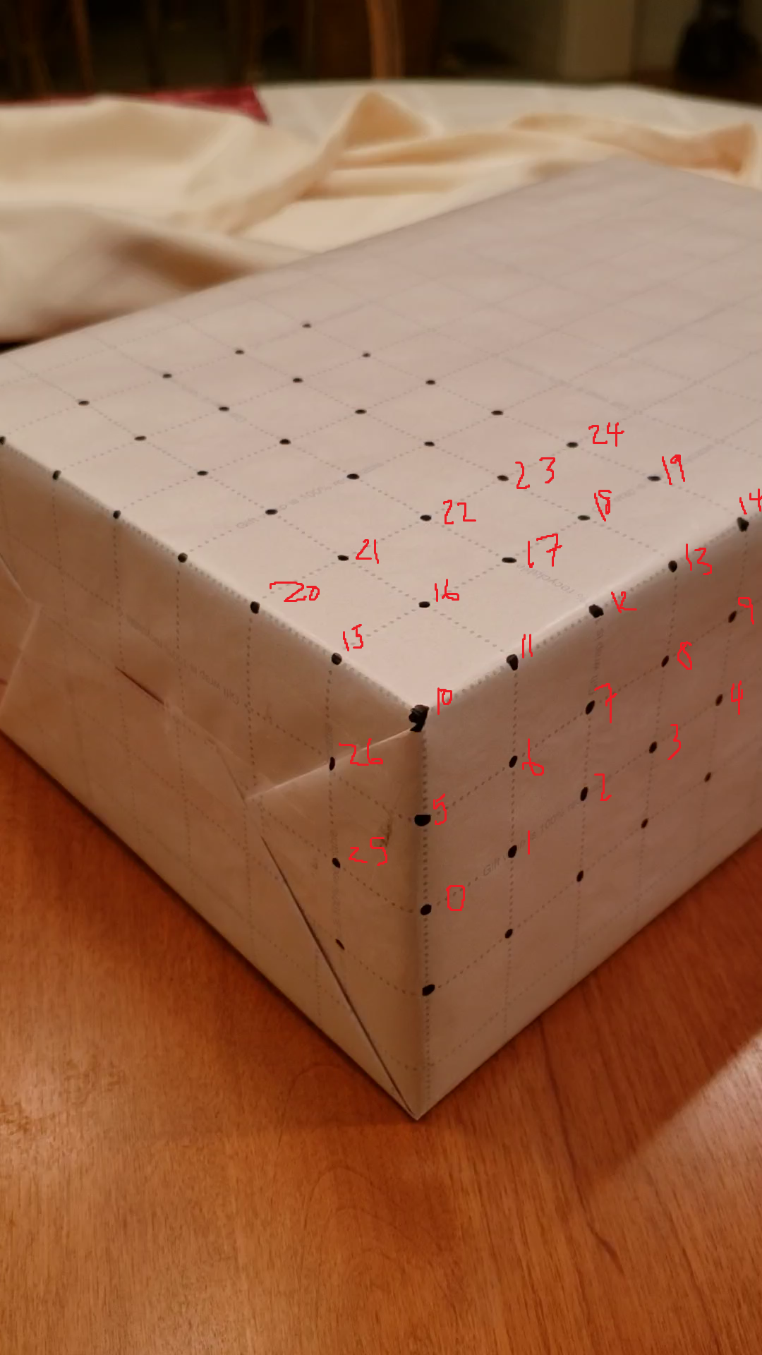
In order to overlay artificial scenes over our video, we need some way to match some notion of world space to some notion of screen space. There's no "true" world space orientation so in general we can select a world space orientation which is useful for our computations. So for instance in this project, if we take a frame of the video, Point 0 that's marked on the box will be \((0, 0, 0)\), and if we impose some canonical identification for our points, we can select a coordinate system appropriately. Here's an example numbering of points for my box on the left.
So with this numbering, we can therefore give each point a world space coordinate. Point 0 would be \((0, 0, 0, 1)\), Point 1 would be \((1, 0, 0, 1)\), Point 5 would be \((0, 1, 0, 1)\), and Point 25 would be \((0, 0, 1, 1)\), all in homogeneous coordinates. Of note here, the grid cells on my wrapping paper are exactly 1 square inch, which is awesome, but actually it turns out we don't particularly care about absolute lengths in world space, only relative coordinates.
Keypoint Tracking
We've basically established a set of key points in the previous part, where each numbered point is a key point. The problem is, we did this once for frame 0, but in a 60 fps video, we would have to do this 60 times just to get one second's worth of key point tracking. Instead we can utilize some OpenCV utilities, namely, the cv2.TrackerMedianFlow. As the name might suggest, this is a prebuilt point tracker, so all we need to do is tell the tracker the bounding boxes of the points we want to track in frame 0, and hopefully if all goes well, the point tracker tracks the key points on our frames. Since we should have gotten the screen space coordinates of our key points with ginput in the previous section, we can use these screen space points to generate our initial bounding boxes, and feed them to our Median Flow Tracker. Here's what our video looks like with the key points tracked.
Calibration
Believe it or not, we're almost done at this point. Once we have our tracked screen space points, since our world space coordinates are static, at this point we have 26 world space points and their 26 mapped screen space points. Actually we may have less than 26 if one of our trackers dropped a point part way through. Regardless we wish to generate our projection matrix that projects world space to screen space. Really this means we just need to solve a linear system of 12 equations, thus with 26 potential mapped points (and therefore 52 mapped coordinates total), we'll employ least squares to compute our projection matrix thus calibrating our camera. With our projection matrix we can now draw something in world space, and see a mapped overlay in screen space! Of course, since the tracked screen space points will change position presumably every frame, this camera calibration algorithm will occur on a per-frame frequency.
Overlays in Augmented Reality
All that's really left to do now is to actually draw our augmented reality overlays. We know where the origin is in world space, so if we want to overlay an axis widget onto our screen, we can project our unit vectors into screen space, and use the cv2 draw functions to render lines. Similarly to overlay a cube, I chose to have the cube base corners as corners 10, 20, 22, and 12. We know the world space coordinates of these 4 points, and we can easily extrapolate the world space coordinates of the four points that make up the upper cap of the cube 2 world space units above each of these base corners. Since we know the projection matrix for each frame, we can project the cube vertices into screen space, and again use the cv2 draw functions to render our cube!
 |  |
Citations
- https://fonts.google.com/specimen/Playfair+Display?selection.family=Playfair+Display|Roboto
- https://www.google.com/
- http://docs.mathjax.org/en/latest/basic/mathematics.html
- https://piazza.com/class/kdktix3lfbx30j?cid=326
- https://inst.eecs.berkeley.edu/~cs194-26/sp20/hw/proj5/ar.html
- https://www.w3schools.com/howto/howto_css_two_columns.asp
- https://inst.eecs.berkeley.edu/~cs194-26/fa20/hw/proj2/
- https://cseweb.ucsd.edu/classes/wi07/cse252a/homography_estimation/homography_estimation.pdf
- http://www.cs.ucf.edu/~mtappen/cap5415/lecs/lec19.pdf
- https://www.learnopencv.com/object-tracking-using-opencv-cpp-python/
- https://docs.opencv.org/3.4/dc/dbb/tutorial_py_calibration.html
- https://docs.opencv.org/3.4/d7/d53/tutorial_py_pose.html
- https://stackoverflow.com/questions/753190/programmatically-generate-video-or-animated-gif-in-python